Taller de IoT
Agenda taller
- Prevención de riesgos
- Factor electrónica
- Factor Arduino
- Factor programación
- Herramientas
- ¡Cacharreo!
- Proyectos Avanzados
Prevención
de Riesgos
Divertida
Photo by Sheffield Hackspace
Electrónica
Factor
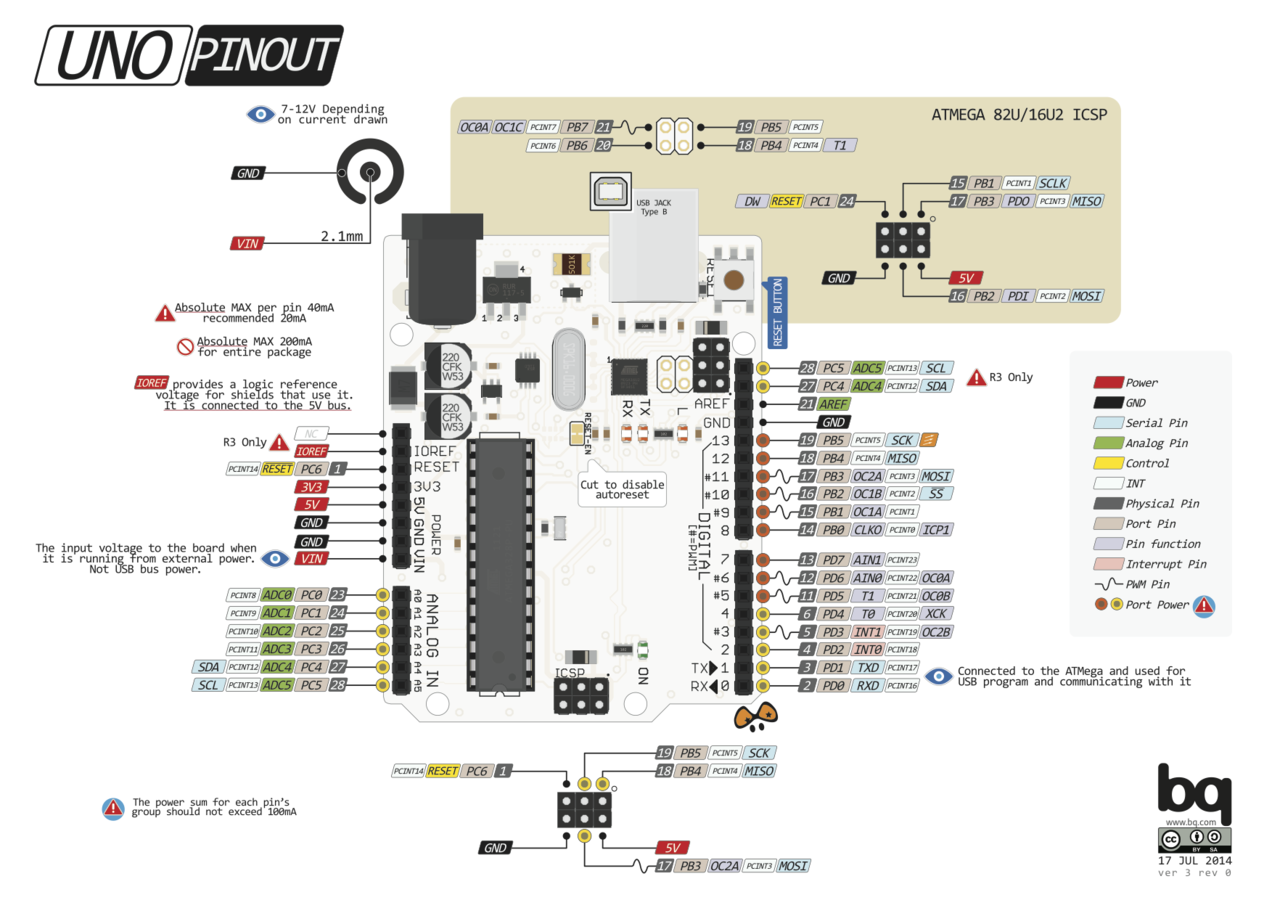
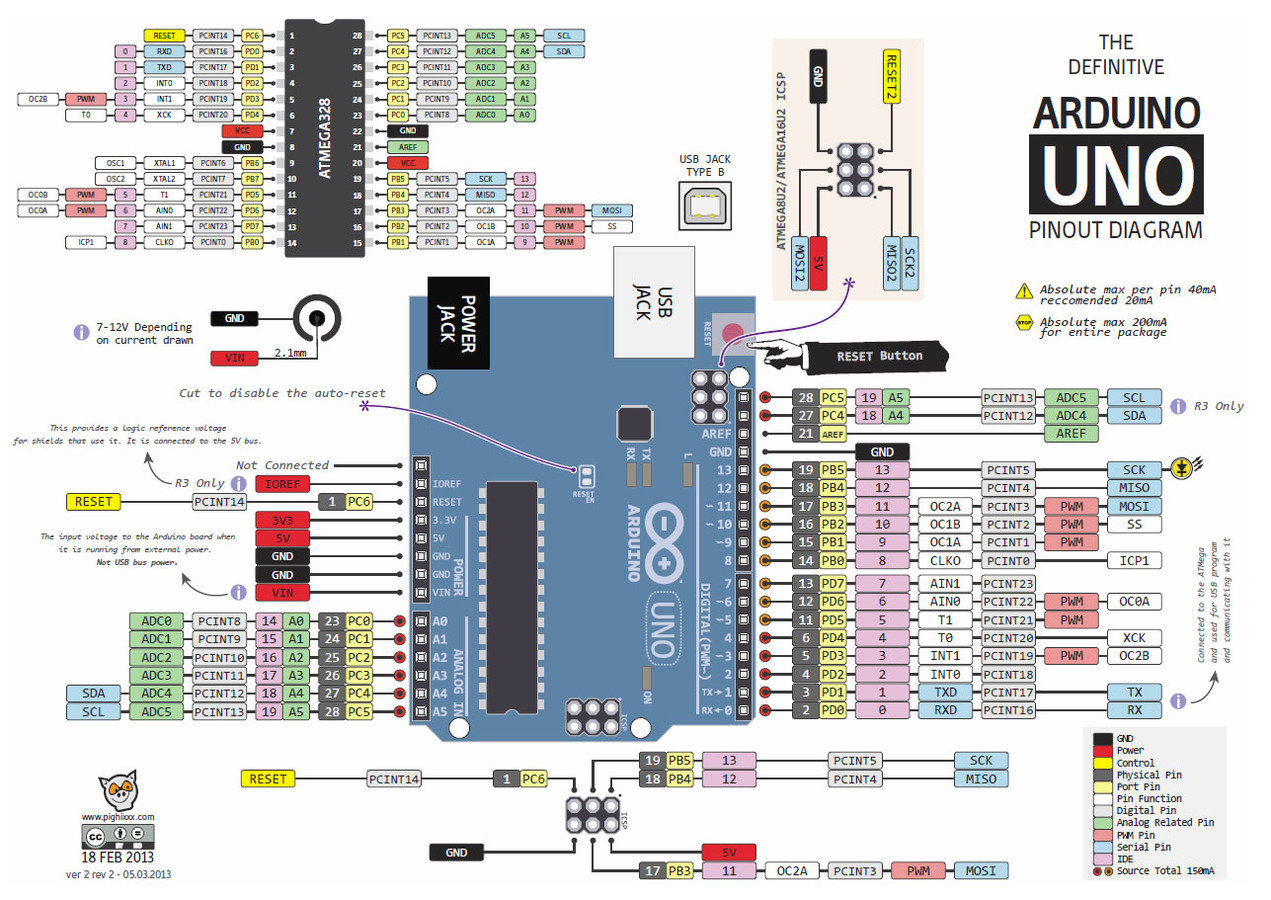
Arduino
Programación
Para Todos


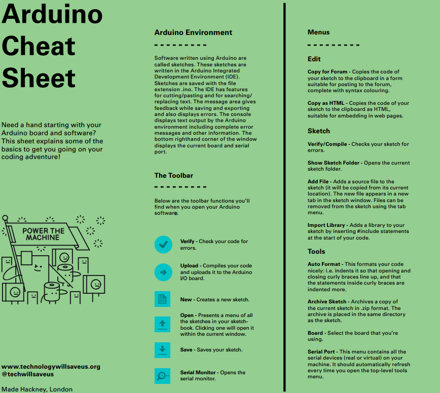
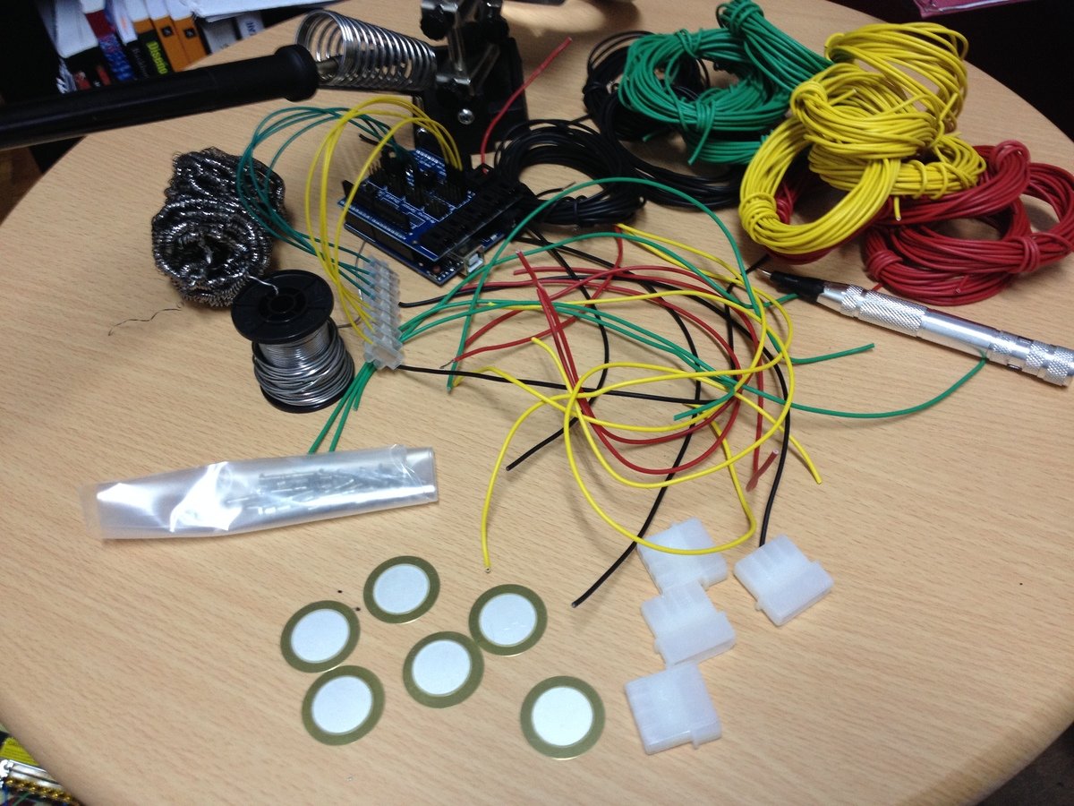
Herramientas
Foto de Hatch Hackerspace


¡Cacharreo!
Photo by FIXME Hackerspace
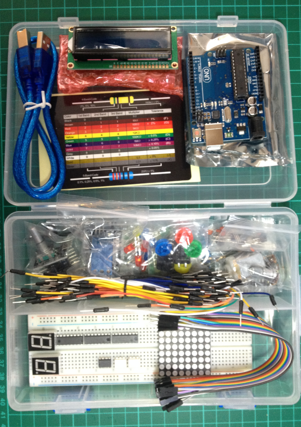
Nuestro Kit
- Arduino UNO
- LCD (2x20)
- Cable USB
- Cables varios
- Botones
- Motor
- Relé
- Potenciómetro
- Matriz Led 8x8
- Leds colores
- Led RGB
- Resistencias
- etc...
Simon Monk

Author of 'Programming Arduino', 'Programming Raspberry Pi', 'Programming BeagleBone Black' and various books on Arduino, Raspberry Pi and Electronics. - Twitter
Prácticas
- Parpadeo LED
- Usando LED RGB
- Combinando LED e interruptores
- RGB e interruptores
- ¡Vamos a la web!
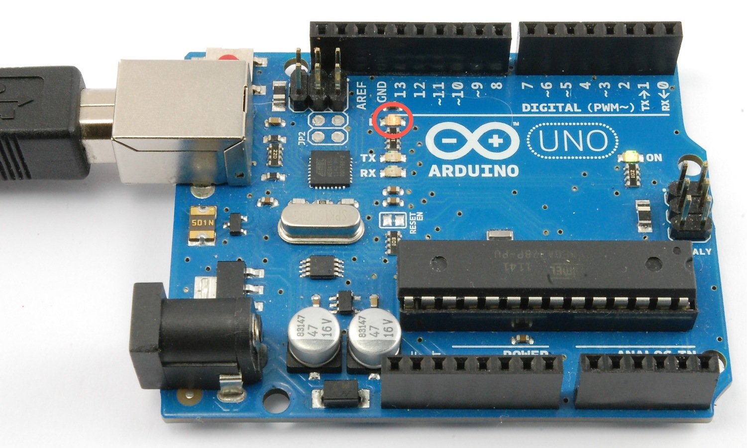
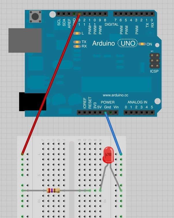
Práctica 1 - Parpadeo Led
Código
/*
  Proyecto: Blink
  Autor: Adafruit
  Referencia: https://learn.adafruit.com/adafruit-arduino-lesson-1-blink/.
  Adaptado por Ulises Gascón
 */

// Usamos el LED que esta conectado por defecto al PIN 13.
// Le ponemos Nombre:
int miLed = 13;

// Setup se ejecuta una vez:
void setup() {
  // Poner el PIN en modo SALIDA.
  pinMode(miLed, OUTPUT);
}

// Loop se ejecutará por siempre:
void loop() {
  digitalWrite(miLed, HIGH);   // Encendemos el LED (Subimos (HIGH) el voltaje)
  delay(1000);               // Esperamos un segundo (1000 milisegundos)
  digitalWrite(miLed, LOW);    // Apagamos el LED (Bajamos (LOW) el voltaje)
  delay(1000);               // Esperamos un segundo (1000 milisegundos)
}
Disponible en GitHub
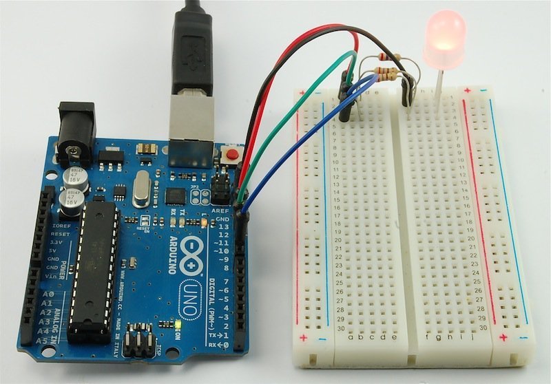
Práctica 2 - Parpadeo Led

Importante
Conexiones
Código
/*
  Proyecto: Blink
  Autor: Adafruit
  Referencia: https://learn.adafruit.com/adafruit-arduino-lesson-1-blink/.
  Adaptado por Ulises Gascón
 */

// Usamos el LED que esta conectado por defecto al PIN 13.
// Le ponemos Nombre:
int miLed = 13;

// Setup se ejecuta una vez:
void setup() {
  // Poner el PIN en modo SALIDA.
  pinMode(miLed, OUTPUT);
}

// Loop se ejecutará por siempre:
void loop() {
  digitalWrite(miLed, HIGH);   // Encendemos el LED (Subimos (HIGH) el voltaje)
  delay(1000);               // Esperamos un segundo (1000 milisegundos)
  digitalWrite(miLed, LOW);    // Apagamos el LED (Bajamos (LOW) el voltaje)
  delay(1000);               // Esperamos un segundo (1000 milisegundos)
}
Disponible en GitHub
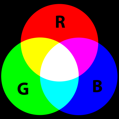
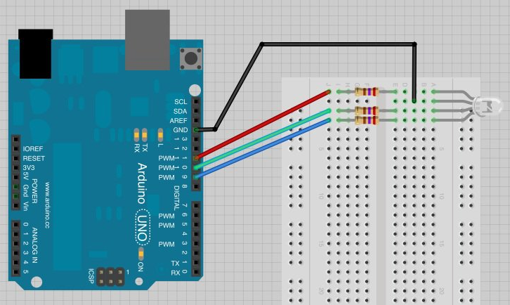
Práctica 3 - LED RGB
Importante
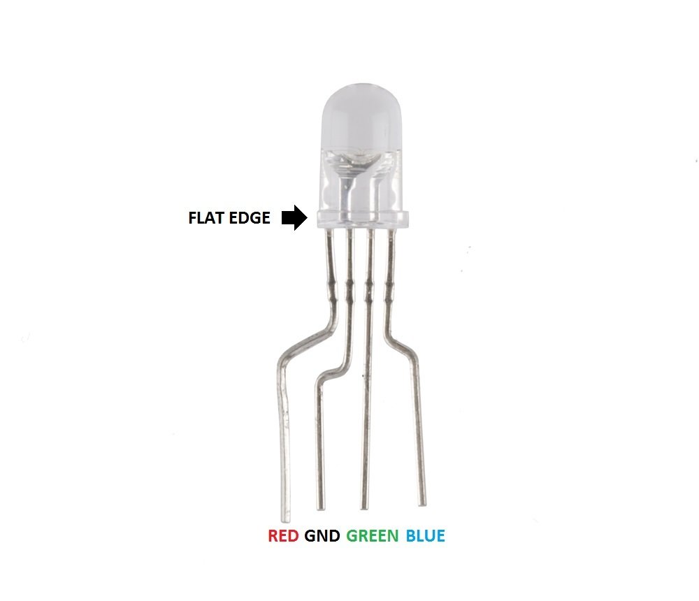
Conexiones
Código
/*
  Proyecto: RGB LED
  Autor: Adafruit
  Referencia: https://learn.adafruit.com/adafruit-arduino-lesson-3-rgb-leds
  Adaptado por Ulises Gascón
*/

int pinRojo = 11;
int pinVerde = 10;
int pinAzul = 9;

void setup()
{
  pinMode(pinRojo, OUTPUT);
  pinMode(pinVerde, OUTPUT);
  pinMode(pinAzul, OUTPUT);
}

void loop()
{
  setColor(255, 0, 0);  // Rojo
  delay(1000);
  setColor(0, 255, 0);  // Verde
  delay(1000);
  setColor(0, 0, 255);  // Azul
  delay(1000);
  setColor(255, 255, 0);  // Amarillo
  delay(1000);
  setColor(80, 0, 80);  // Púrpura
  delay(1000);
  setColor(0, 255, 255);  // Azul agua
  delay(1000);
}

void setColor(int rojo, int verde, int azul)
{
  analogWrite(pinRojo, rojo);
  analogWrite(pinVerde, verde);
  analogWrite(pinAzul, azul);
}
Disponible en GitHub
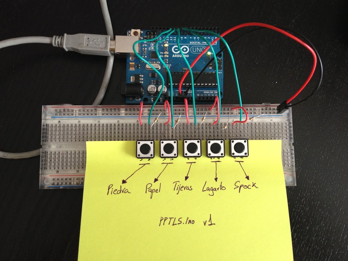
Práctica 4 - Led y botones
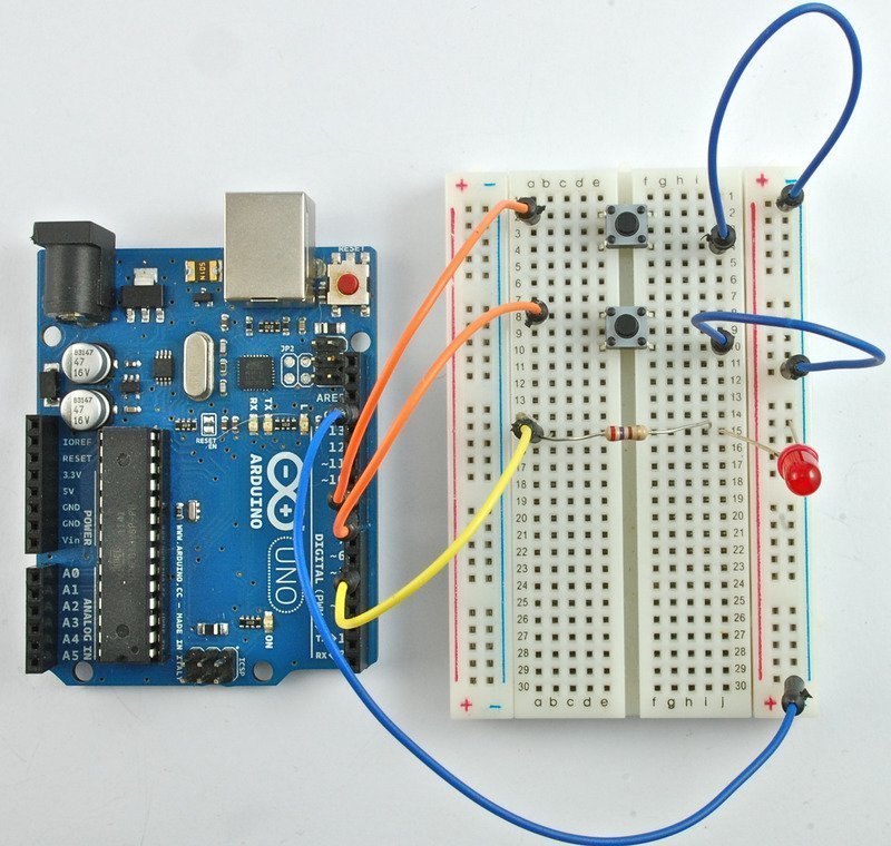
Importante
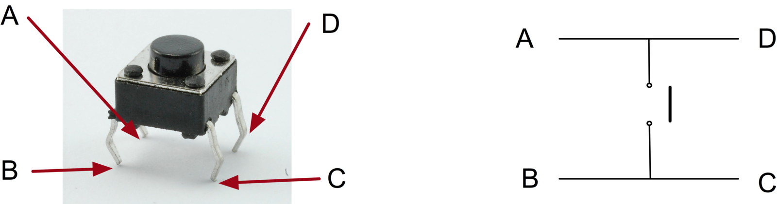
Conexiones
Código
/*
  Proyecto: Inputs
  Autor: Adafruit
  Referencia: https://learn.adafruit.com/adafruit-arduino-lesson-6-digital-inputs
  Adaptado por Ulises Gascón
*/
int pinLed = 5;
int pinBotonA = 9;
int pinBotonB = 8;

byte leds = 0;

void setup()
{
  pinMode(pinLed, OUTPUT);
  pinMode(pinBotonA, INPUT_PULLUP);
  pinMode(pinBotonB, INPUT_PULLUP);
}

void loop()
{
  if (digitalRead(pinBotonA) == LOW)
  {
    digitalWrite(pinLed, HIGH);
  }
  if (digitalRead(pinBotonB) == LOW)
  {
    digitalWrite(pinLed, LOW);
  }
}
Disponible en GitHub
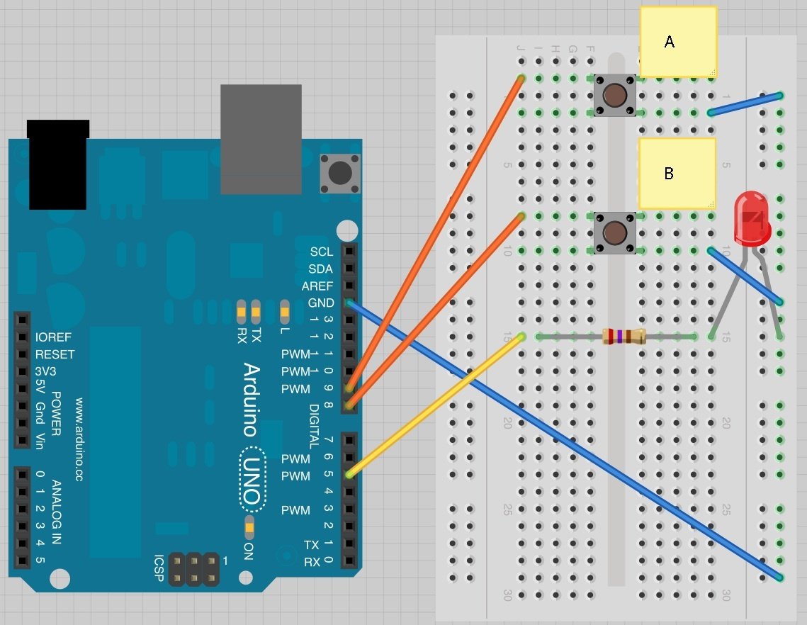
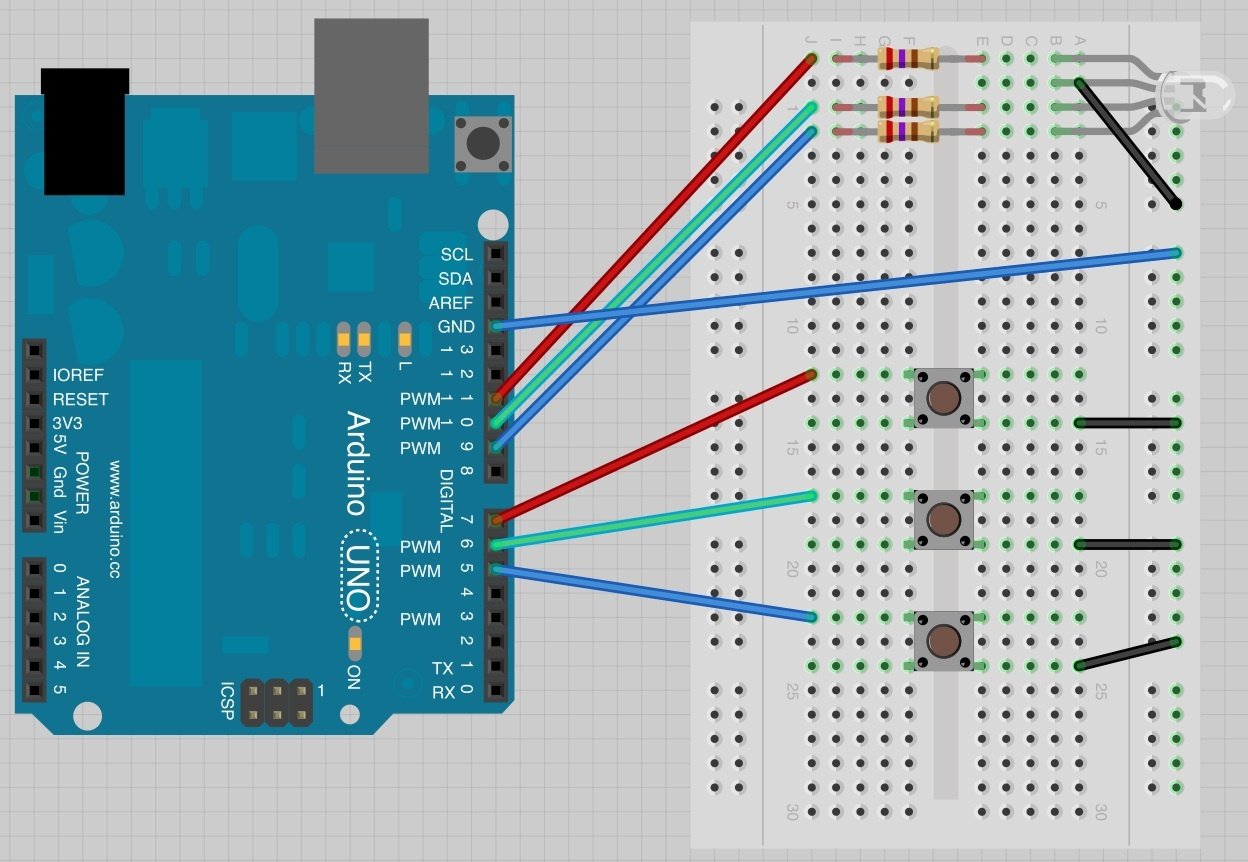
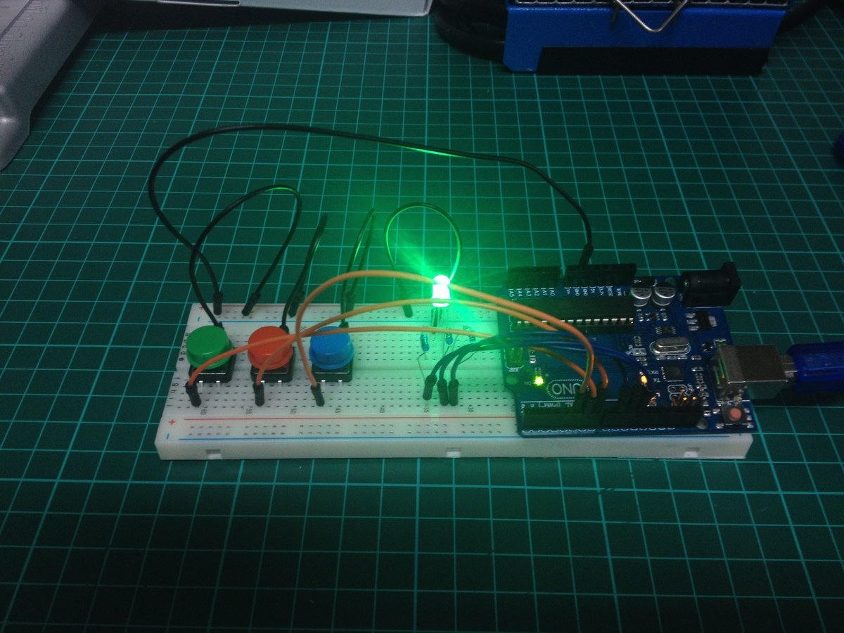
Práctica 5 - RGB y botones
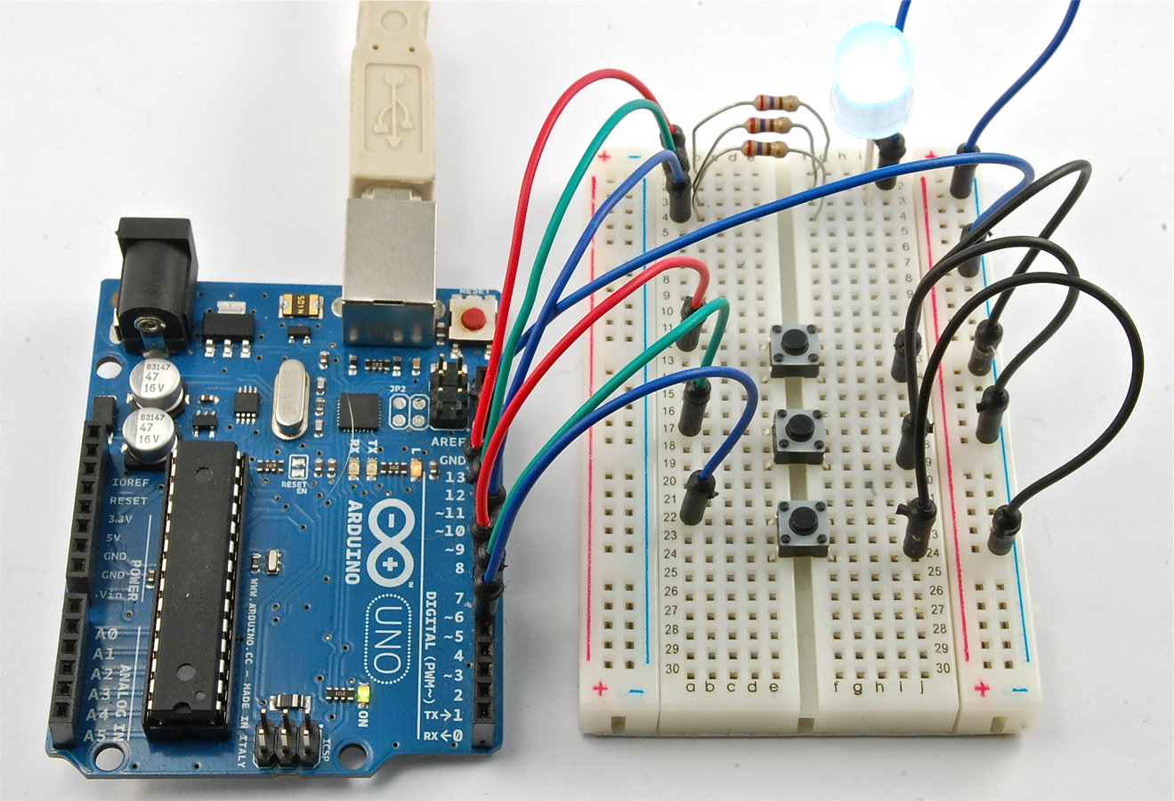
Conexiones
Código
/*
  Proyecto: RGB Fader
  Autor: Adafruit
  Referencia: https://learn.adafruit.com/adafruit-arduino-lesson-7-make-an-rgb-led-fader
  Adaptado por Ulises Gascón
*/

int pinLedRojo = 11;
int pinLedVerde = 10;
int pinLedAzul = 9;

int pinInterruptorRojo = 7;
int pinInterruptorVerde = 6;
int pinInterruptorAzul = 5;

int valorRojo = 0;
int valorAzul = 0;
int valorVerde = 0;

void setup()
{
  pinMode(pinLedRojo, OUTPUT);
  pinMode(pinLedVerde, OUTPUT);
  pinMode(pinLedAzul, OUTPUT);
  pinMode(pinInterruptorRojo, INPUT_PULLUP);
  pinMode(pinInterruptorVerde, INPUT_PULLUP);
  pinMode(pinInterruptorAzul, INPUT_PULLUP);
}

void loop()
{
  if (digitalRead(pinInterruptorRojo) == LOW)
  {
    valorRojo ++;
    if (valorRojo > 255) valorRojo = 0;
  }
  if (digitalRead(pinInterruptorVerde) == LOW)
  {
    valorVerde ++;
    if (valorVerde > 255) valorVerde = 0;
  }
  if (digitalRead(pinInterruptorAzul) == LOW)
  {
    valorAzul ++;
    if (valorAzul > 255) valorAzul = 0;
  }
  analogWrite(pinLedRojo, valorRojo);
  analogWrite(pinLedVerde, valorVerde);
  analogWrite(pinLedAzul, valorAzul);
  delay(10);
}
Disponible en GitHub
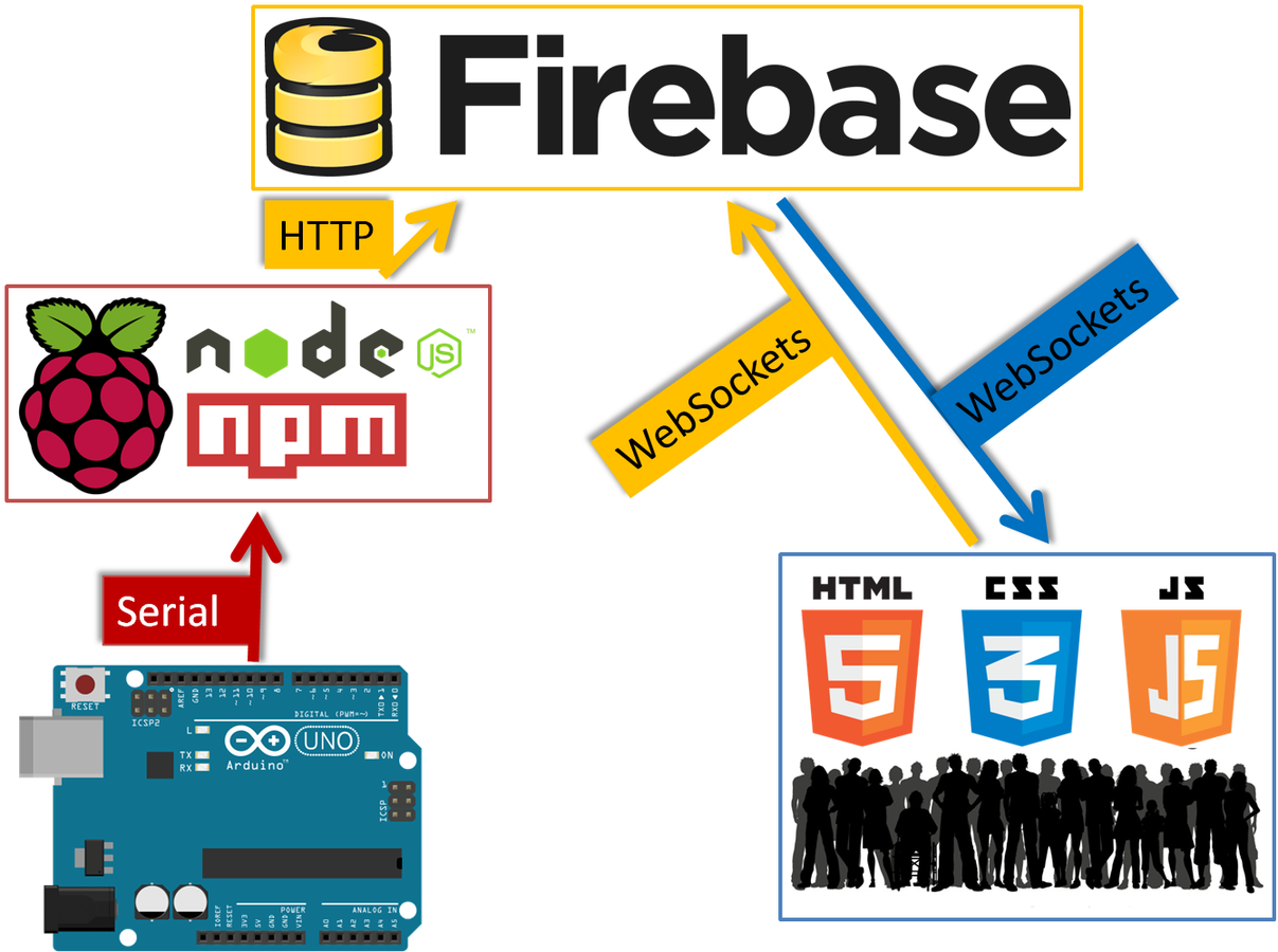
Práctica 6 - ¡Vamos a la web!
Código
/*
  Proyecto: RGB Fader to Firebase
  Autor Original: Adafruit
  Referencia: https://learn.adafruit.com/adafruit-arduino-lesson-7-make-an-rgb-led-fader
  Adaptado por Ulises Gascón
*/

int pinLedRojo = 11;
int pinLedVerde = 10;
int pinLedAzul = 9;

int pinInterruptorRojo = 7;
int pinInterruptorVerde = 6;
int pinInterruptorAzul = 5;

int valorRojo = 0;
int valorAzul = 0;
int valorVerde = 0;

void setup()
{
  // Serial
  Serial.begin(9600);

  pinMode(pinLedRojo, OUTPUT);
  pinMode(pinLedVerde, OUTPUT);
  pinMode(pinLedAzul, OUTPUT);
  pinMode(pinInterruptorRojo, INPUT_PULLUP);
  pinMode(pinInterruptorVerde, INPUT_PULLUP);
  pinMode(pinInterruptorAzul, INPUT_PULLUP);
}

void loop()
{
  if (digitalRead(pinInterruptorRojo) == LOW)
  {
    valorRojo ++;
    if (valorRojo > 255) valorRojo = 0;
  }
  if (digitalRead(pinInterruptorVerde) == LOW)
  {
    valorVerde ++;
    if (valorVerde > 255) valorVerde = 0;
  }
  if (digitalRead(pinInterruptorAzul) == LOW)
  {
    valorAzul ++;
    if (valorAzul > 255) valorAzul = 0;
  }
  analogWrite(pinLedRojo, valorRojo);
  analogWrite(pinLedVerde, valorVerde);
  analogWrite(pinLedAzul, valorAzul);

  // JSON
  String jsonSerial = "{";
  jsonSerial += "\"azul\":";
  jsonSerial += valorAzul;
  jsonSerial += ", \"rojo\":";
  jsonSerial += valorRojo;
  jsonSerial += ", \"verde\":";
  jsonSerial += valorVerde;
  jsonSerial += "}";
  // Impresión
  Serial.println(jsonSerial);

  delay(100);
}
Disponible en GitHub
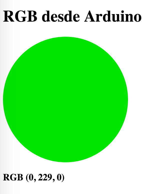
Resultado
WEB

Proyectos
Avanzados
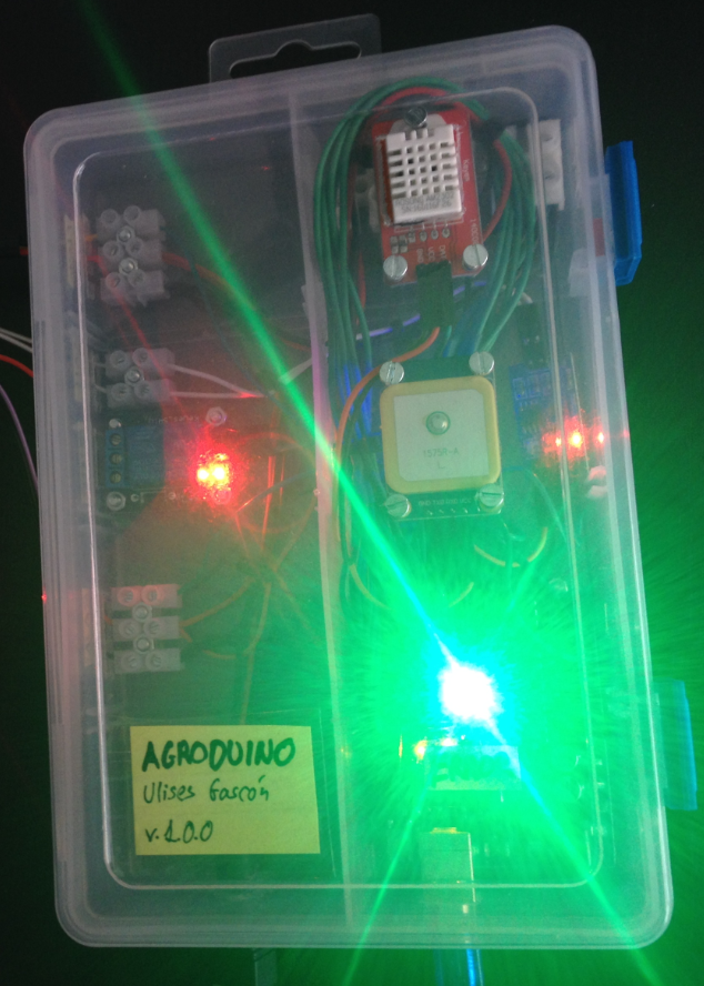
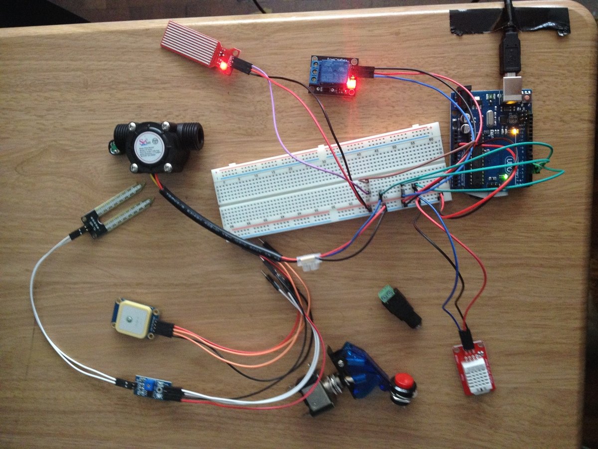
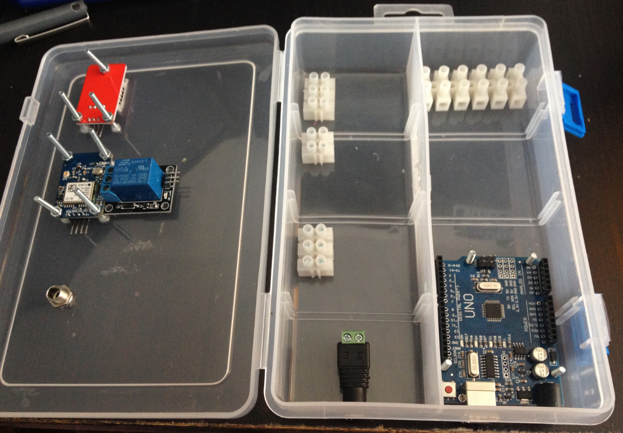
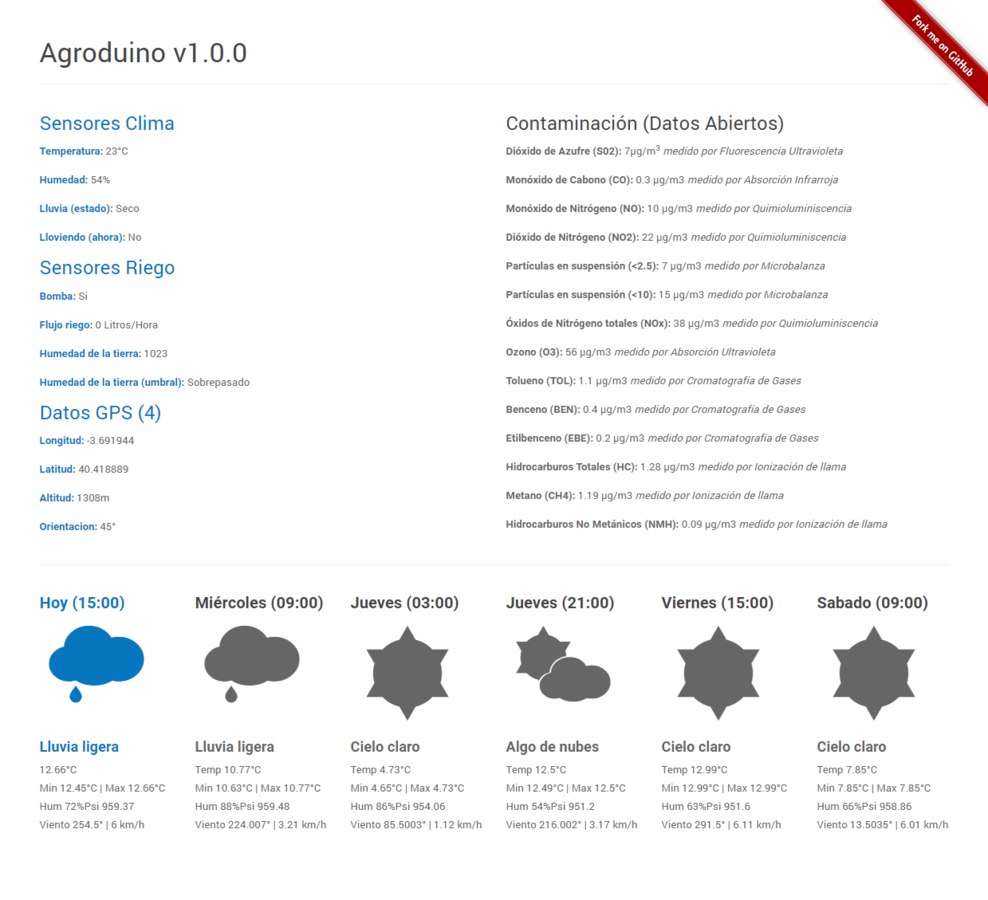
Agroduino (2016, Ulises Gascón)

Código y Diseños: Github | Licencia: GNU GPL v3
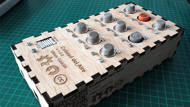
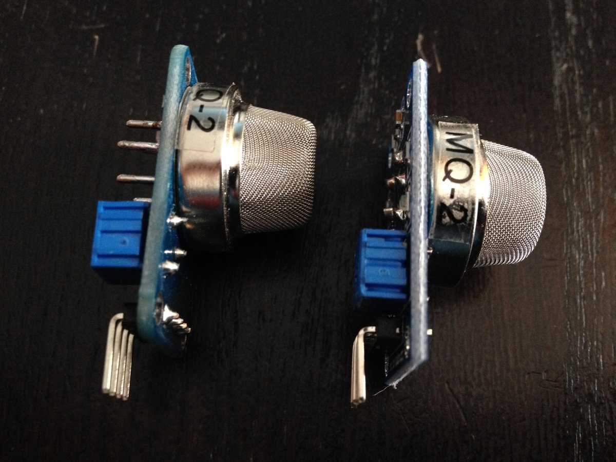
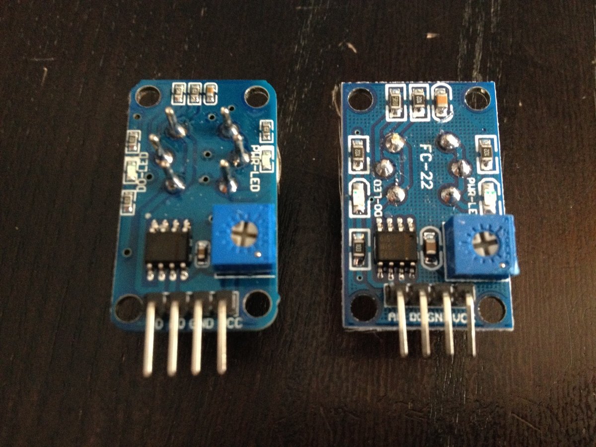
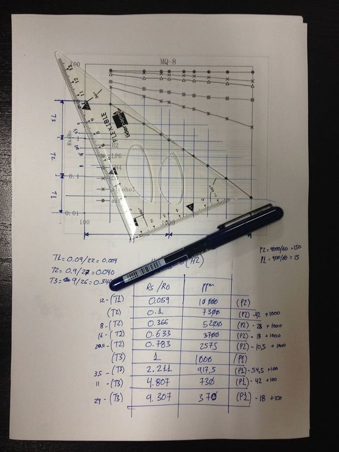
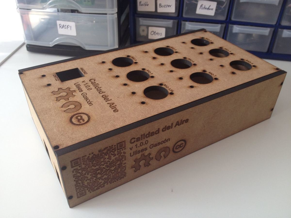
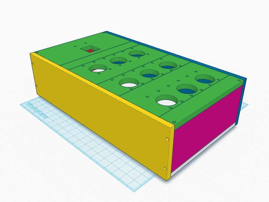
Calidad del Aire (2016, Ulises Gascón)
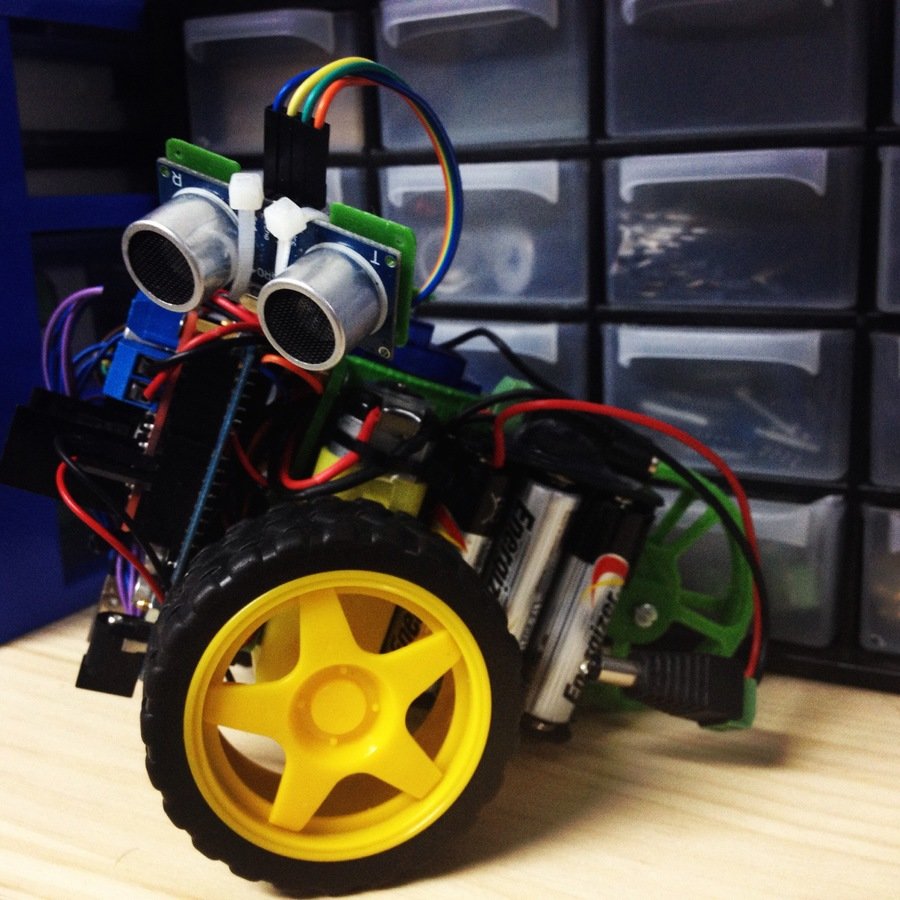
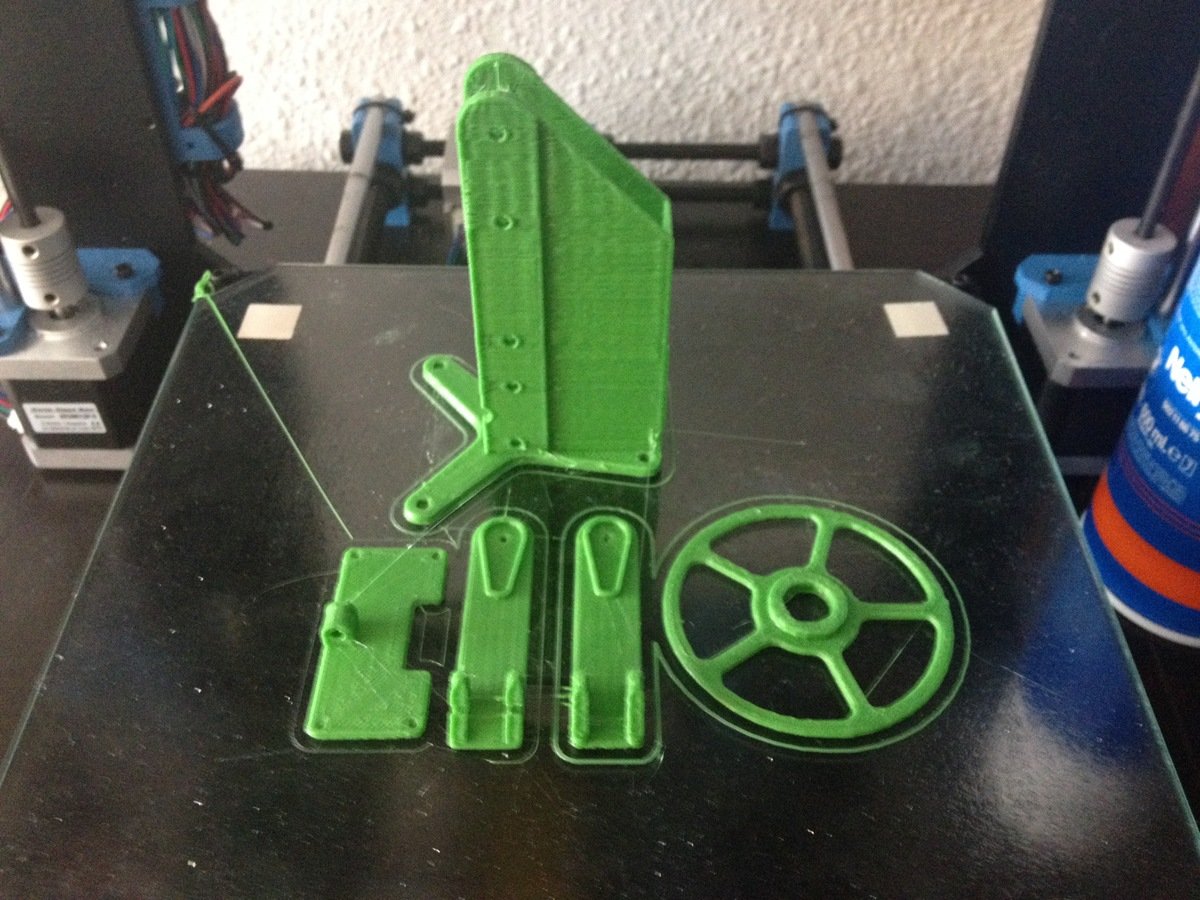
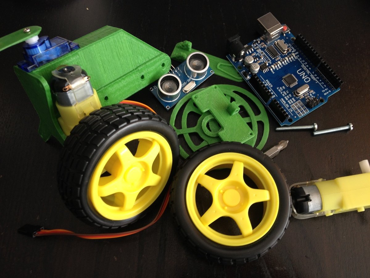
SCRU FE (2016, Ulises Gascón)
Código y Documentación: Github | Piezas: Thingverse | Licencia: CC-BY-SA
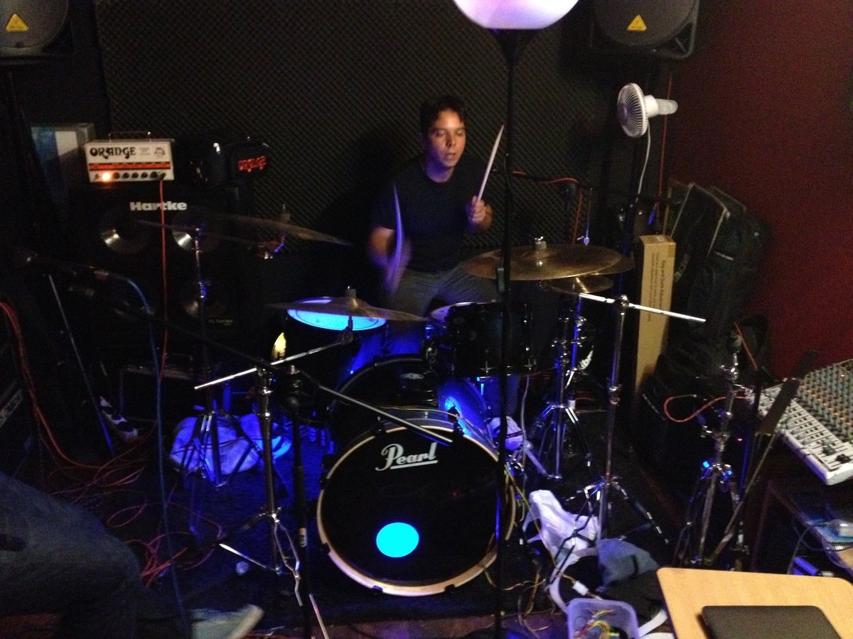
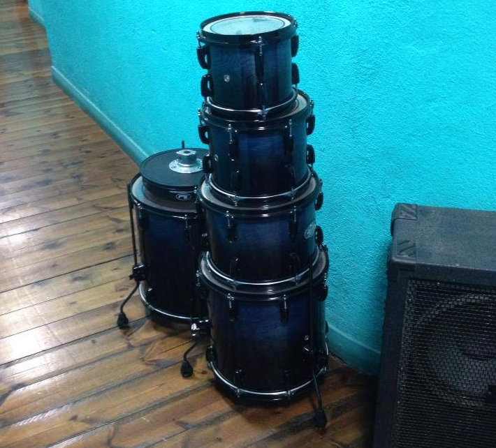
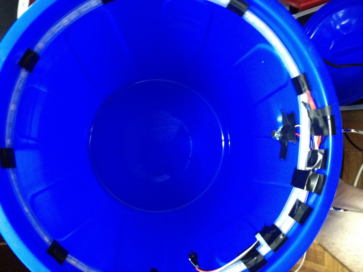
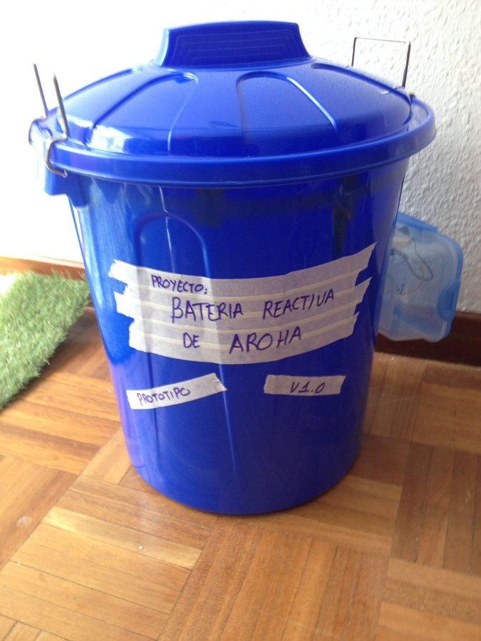
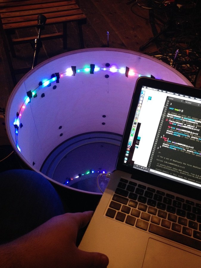
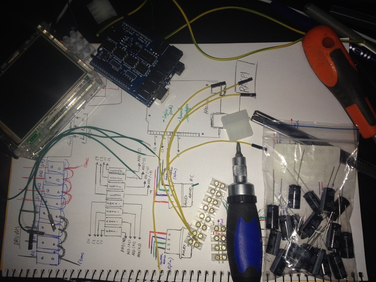
Batería Reactiva (2015, Ulises Gascón)
Código y Documentación: Github | Licencia: GNU GPL v3


Reloj Binario (2015, Ulises Gascón)
¡Gracias!
Los sueños son sumamente importantes. Nada se hace sin que antes se imagine.
- George Lucas